Apollo Fuel Cell
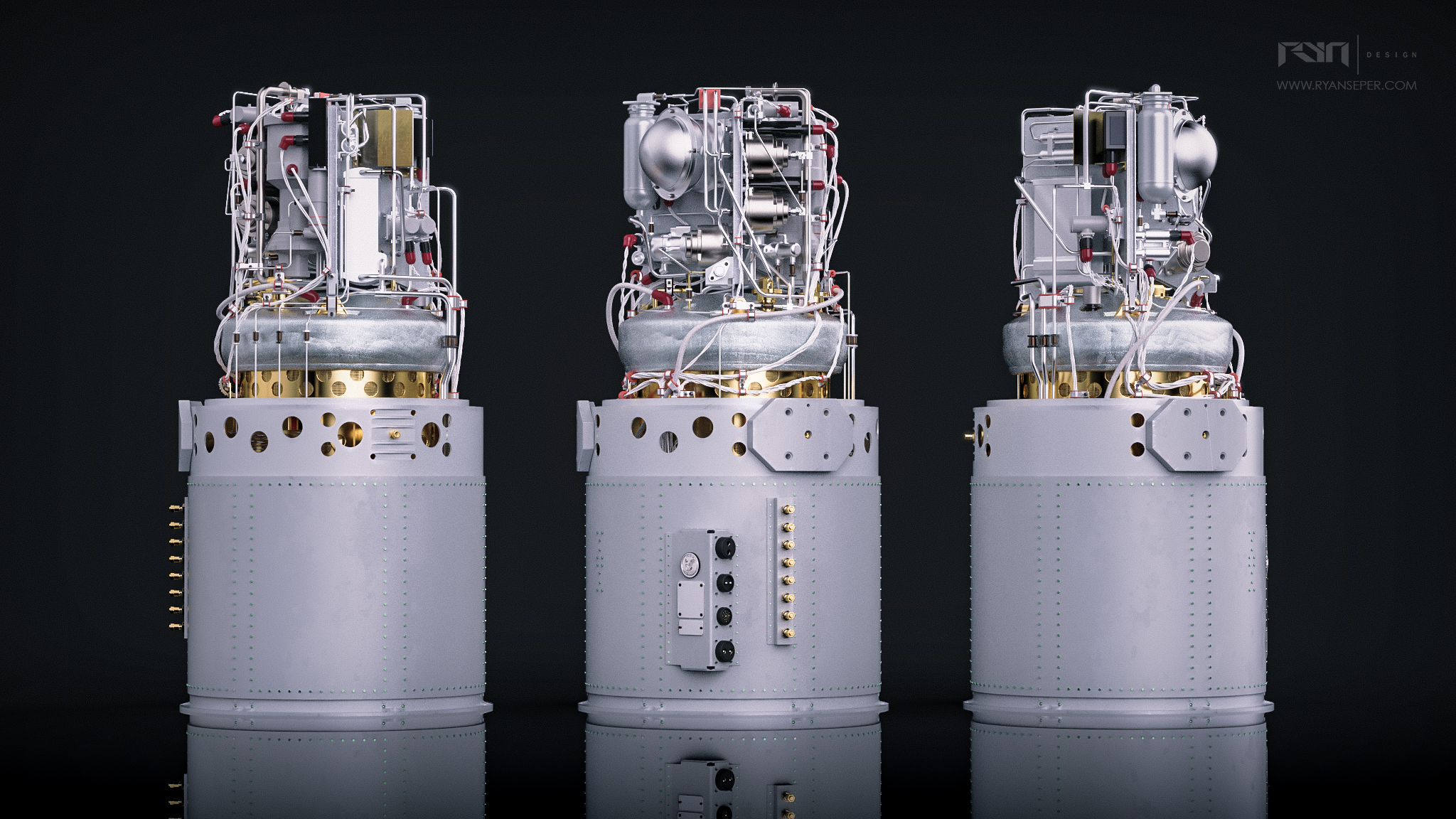
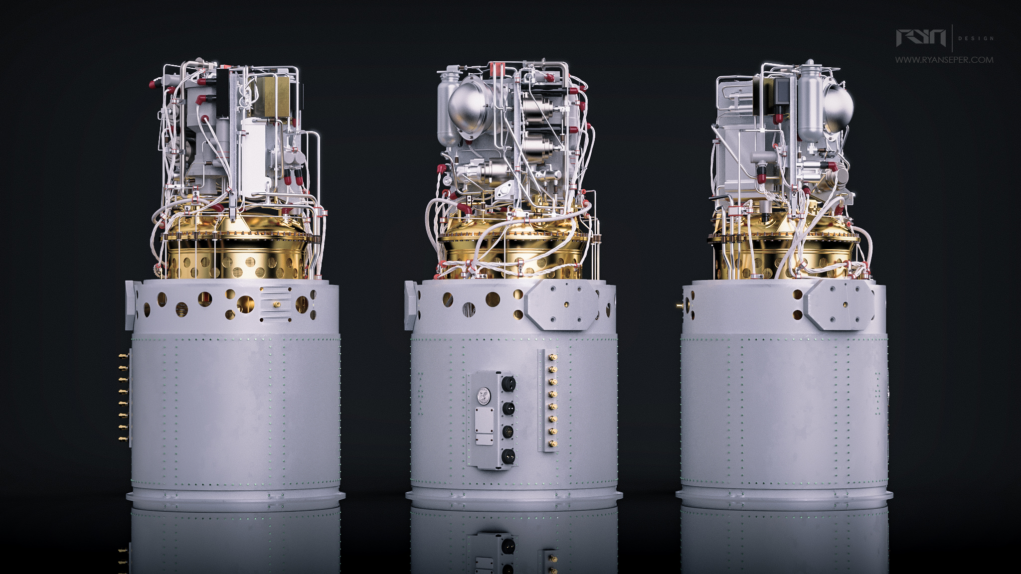


How do you generate power in space?
During NASA’s Apollo space program a fuel cell created by United Aircraft Corporation’s Pratt & Whitney Aircraft Division was utilized to generate power on board the Command and Service Module (CSM). The fuel cell utilizes hydrogen, oxygen, and nitrogen to create a chemical reaction that yields electricity, and drinkable water. Quite a useful tool for space travel. During my initial research I came across the Apollo Spacecraft News Reference document (for Apollo 12), that NASA released. It is a comprehensive review of the mission and technical systems that made the trip to the moon possible. News corporations could then distill and inform the public with this information. The detail provided by this document allowed me to understand how the fuel cell operated on a system level. See below for a brief description of the fuel cells.
“Three fuel cell powerplants, each 44 inches high, 22 inches in diameter, and weighing 245 pounds, are located in Sector 4 of the SM [Support Module] . They are mainly constructed of titanium, stainless steel, and nickel. They are rated at 27 to 31 volts under normal loads. There are 31 separate cells in a stack, each producing 1 volt, with potassium hydroxide and water an electrolyte. Each cell consists of a hydrogen and an oxygen electrode, a hydrogen and an oxygen gas compartment, and the electrolyte. Each gas reacts independently to produce a flow of electrons. The fuel cells are nonregenerative. They are normally operated at 400 degrees F with limits of 385 and 500 degrees. Water-glycol is used for temperature control. The fuel cells use hydrogen, oxygen, and nitrogen under regulated pressure to produce power and, as a by-product, water.”
Rebuilding the Fuel Cell
My goal for this project was to recreate a 3D model in Solidworks of the Apollo Fuel Cell. This model would help develop my understand of complex assemblies within Solidworks, as well as my ability to breakdown a design from a 2D image and recreate it in 3D. This was done through research on technical documents (like the one quoted above) as well as analysis of photographs. During this project I had no physical access to a fuel cell and as such it was particularly challenging solving the visual “puzzle” of the fuel cell. It has many interlinked pipes routed throughout, to complicate things over the years many variations of parts were created as the design was improved so certain images I was looking at would have different parts. The model I created was based on the most common configurations I found as well as the units that appeared to be in the best condition (not disassembled or broken) Having said that the overall dimensions match the official NASA documents, but I’d estimate individual components may be around 90% accurate to the real thing. Regardless, I believe this to be a highly accurate representation of the Apollo-era fuel cell. I was continually amazed at the level of engineering and design possible in the 1960s to produce a device such as this all without the usage of the modern day CAD tools we use today.
Collecting Visual Research
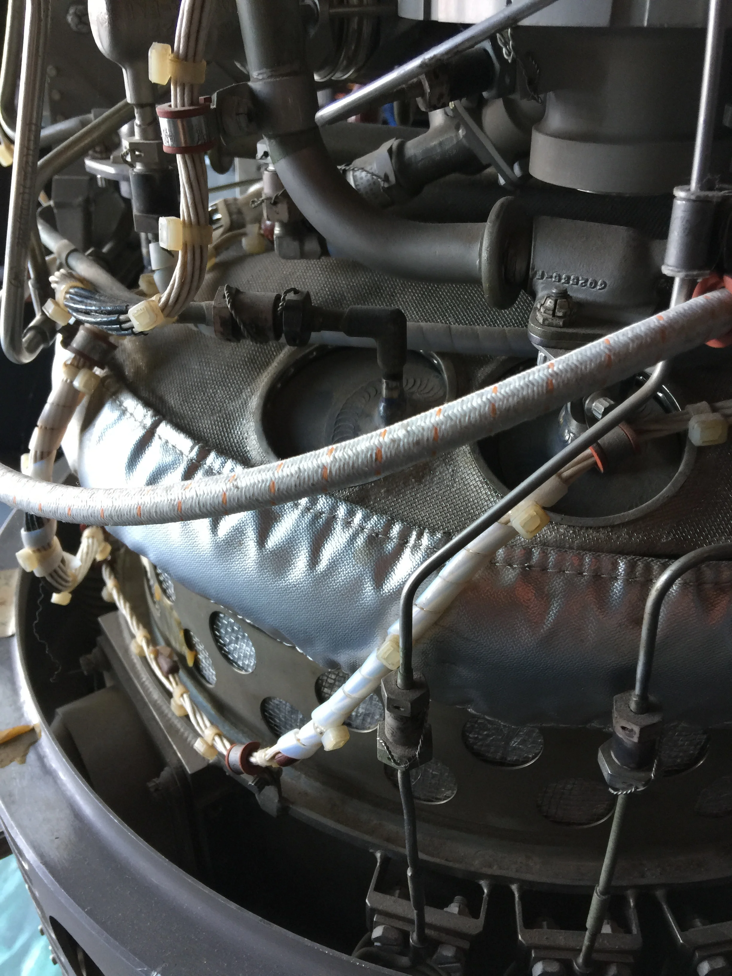
Below is a small selection of some of the images I used for building the fuel cell. Initially I had filtered out all low resolution photos in favor of higher quality images. But eventually I started missing major features of the fuel cell and eventually had to settle for lower quality images that provided angles / views I hadn’t previously seen. Thankfully, Joe Hiura was able to provide me with some great photos of close ups and unique angles of his fuel cell, along with providing a wealth of feedback on the project along the way. Every pipe connection had to be tracked through the catalog of photos, and the schematics provided by the Apollo Spacecraft News Reference document. I utilized a great piece software, PureRef , along the way to correlate my images, and review them quickly when I modeled.
The Fuel Cell’s role in Apollo 13
During Apollo 13 a liquid oxygen tank below the fuel cells ignited and ruptured within the service module. The mechanical shock of this rupture caused enough damage that the crew began to notice oxygen leaking out of the support module. Eventually ground control made the decision to shut down all fuel cells to prevent any additional leaking. Without means of generating power the crew had to utilize the limited battery power stored in the Command Module and Lunar Modules(LM). They also had to ration their intake of water, as the LM served as a “lifeboat” for their trip back.


Engineering Drawings
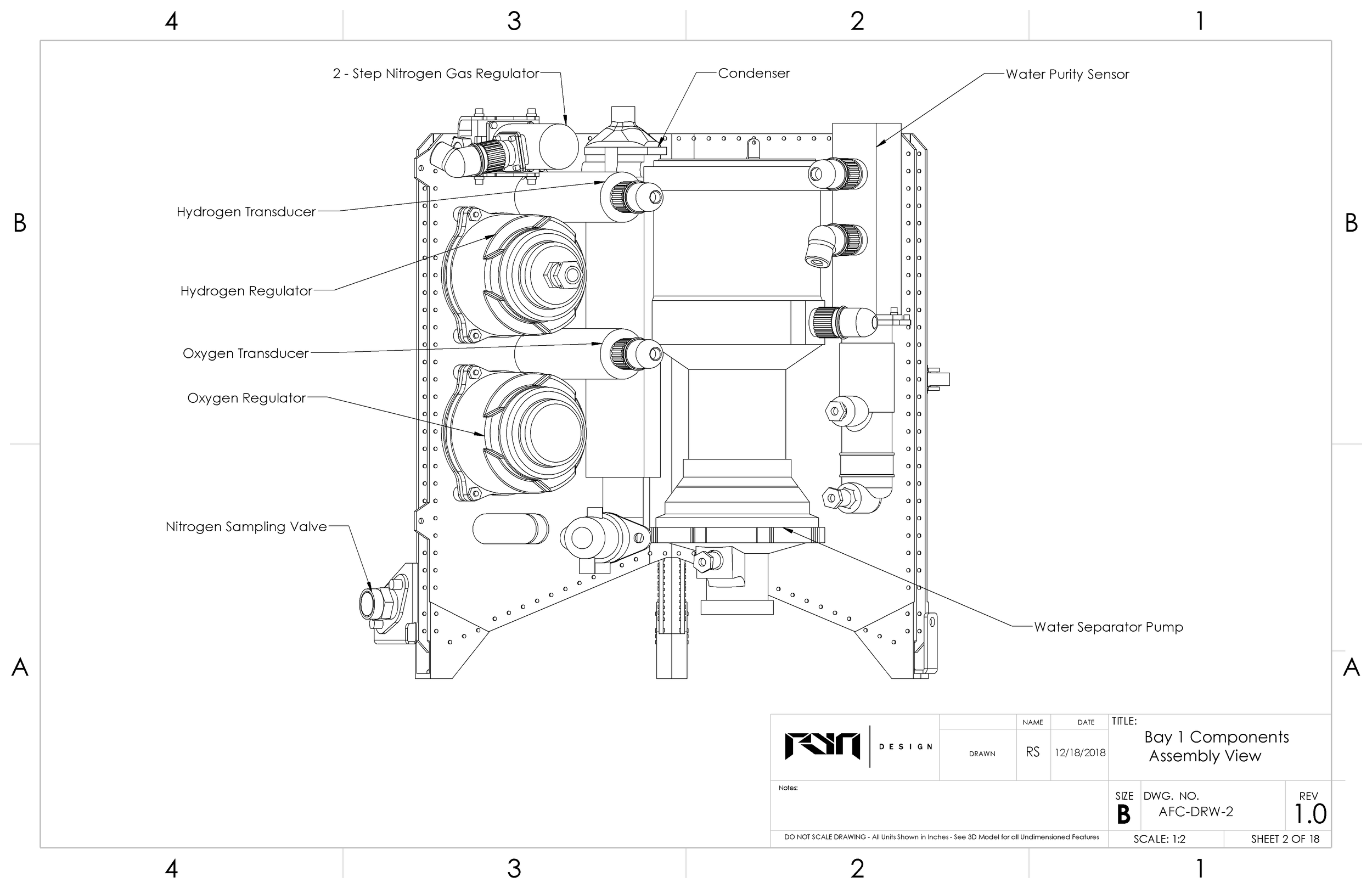
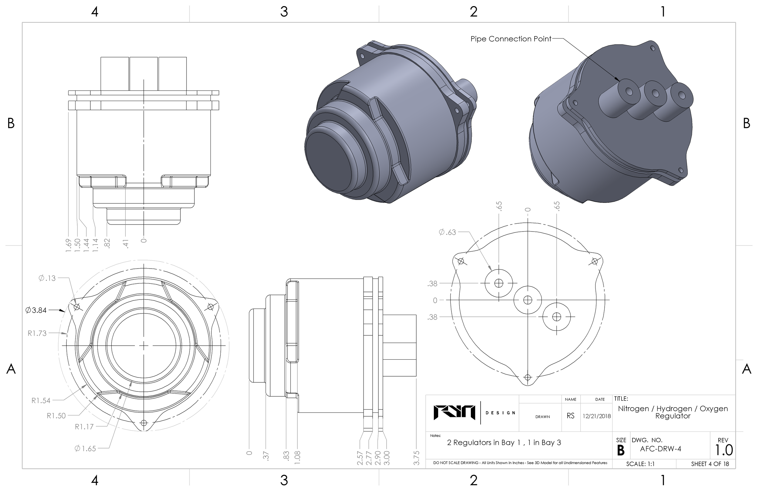
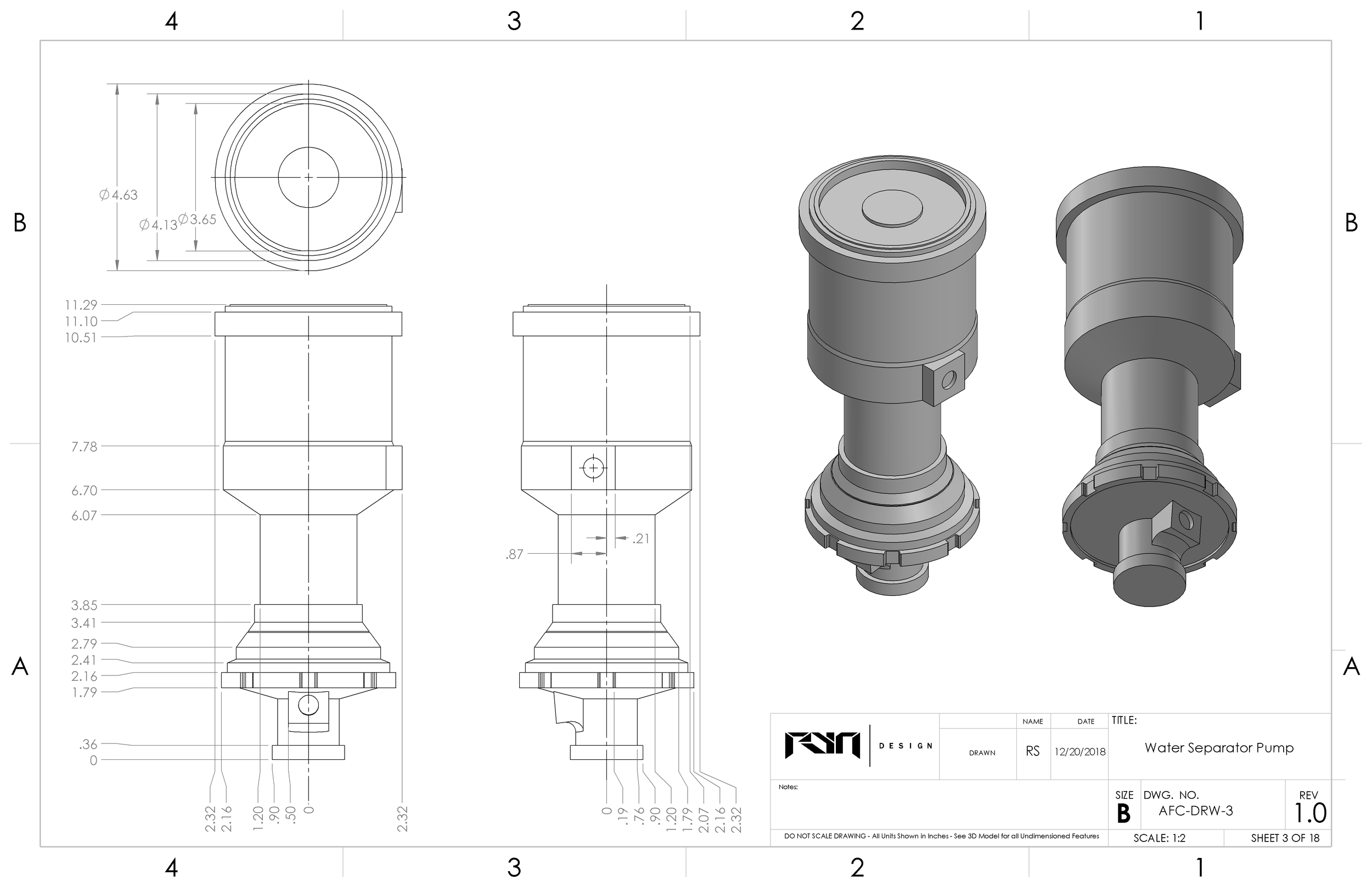
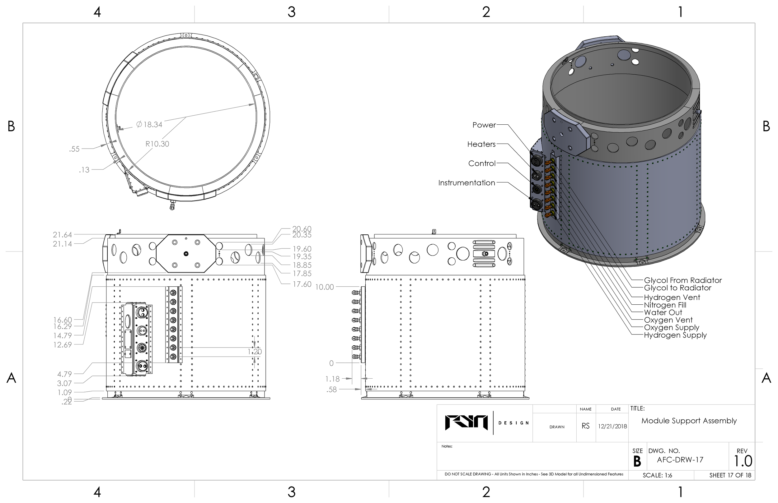
To finish the project I created engineering drawings for the major parts on the fuel cell. Creating engineering drawings is often the least exciting part of the process but necessary for turning digital designs into real world parts. Below is a selection of a few of the drawings made.

Closing Comments
If you’ve read this far thanks for taking the time to review everything and I hope I’ve provided you with a better understanding of an incredible piece of machinery that helped man reach the moon. The project as a whole took a large investment of time, but was well worth the experience gained, and lessons learned. If you have any feedback, or advice, for improving this project please don’t hesitate to reach out to me via email (ryanseper@gmail.com)
A .STEP file of this model is available on my gumroad page for FREE for personal usage only. https://gumroad.com/l/PYApF
Special thanks to Joe Hiura for his feedback and support along the way, the engineers that worked on this Fuel Cell at United Aircraft Corporation’s Pratt and Whitney Division, and all the teams at NASA whose innovation continues to inspire and push the boundaries of what is possible.

